AADE DFD2 Diagnosis

DFD2 Instructions

Checking 445 kHz IF Offset || Checking the VFO Input || Checking the Crystal Oscillator (HFO) Input
Frequency Table || Accurate Readout

The first step in diagnosing a problem with the DFD2 counter is to make sure proper connections have been made between the boards and the counter.

There are two connections to the board. One to the VFO and one to the Crystal Oscillator.

The following picture shows the connection to the VFO. See AADE DFD2 VFO Connection for more information.

The following picture shows the connection to the Crystal Oscillator.
See AADE DFD2 HFO Connection for more information.

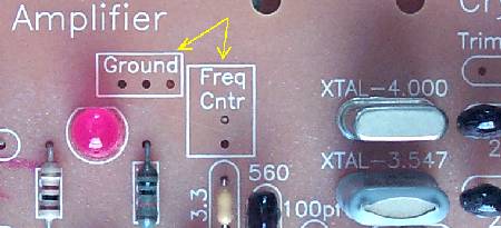
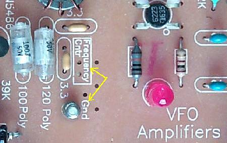
For more information on the connections, see "Connecting the Frequency Counter to the Receiver"
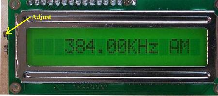
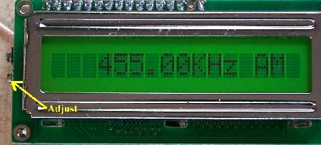
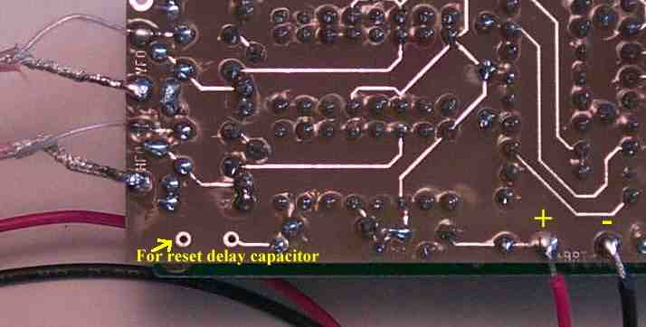
Checking 445 kHz IF Offset

When you check your frequencies in the following steps, remember that they will be plus or minus 455 kHz, depending on the band you are checking. These offsets will be noted in the following descriptions.

The following will go over the proper setting of the 455 kHz IF offset, then the connection to the VFO and the Crystal Oscillator.

Have a set of clip leads so you can use it to ground the inputs to the frequency counter for testing the frequencies that are being input to the counter.

Or, you may remove the 74HC4046s as noted below. I found this a lot easier to do if you have not mounted the counter in a permanent place. Also, it will help you find a bad 74HC4046 chip. The bad one will show different readings than a good one.

Always double check that you have mounted the chip correctly in the socket before powering up the display!
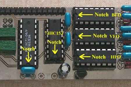

The VFO and HFO inputs are the bottom two connections as shown above. The top one is the BFO and it should have a wire between the input and ground. Or, the 74HC4046 in the top socket, which inputs to the BFO, may be removed.

If you have not mounted the DFD2, pull off the display and remove all the 74HC4046 ICs. This is easier than trying to ground the inputs and more reliable. You will have to bend the .01 caps slightly forward to get a small screwdriver under the chips to remove them.

Check for 455 kHz at all band positions. If not, adjust the trimmer pots as follows:

First, make sure the reading is 0 kHz. This is done by turning the trimpots all the way counter-clockwise.

____First, turn the coarse pot (upper one) clockwise to 384 kHz.

____Second, turn the fine pot (lower one) clockwise to reach 455 kHz.

If you do not get 455kHz on all bands, or the 455kHz adjustments do not work, the PIC16C71 is bad.


Checking the VFO Input

Unhook the ground clip lead to the VFO input. Leave the ground clip lead hooked to the HFO (Crystal Oscillator) input.

Or, put a 74HC4046 into the middle socket on the right side of the PCB. This is the VFO input. Other sockets should be empty.

The frequencies read by the counter should be as follows:

Band Display Reads MHz VFO Freq MHz Bottom Jumper Volts What it does
40 11.002 10.547 4.5 +455
30 13.613 14.068 0 -455
20 10.002 10.457 0 -455
17 14.523 14.068 4.5 +455

Check your VFO frequencies to make sure they are the same or close to the above values under "VFO Freq". Measure the VFO frequency at the "VFO OUT" box between the VFO amplifiers.

If you are still getting 455 kHz, then the counter is not receiving the VFO signal. If the reading is varying a lot, then the counter is not getting a strong enough signal to read the VFO. Check for good connections, the 3.3pf cap connecting to the VFO and the counter shorting to ground, or raise the value of the 3.3pf coupling cap to 10pf or so.

If your readings vary between 74HC4046 chips, then one or all of the 74HC4046s are bad. I recommend replacing all the 74HC4046 and the 74HC153 chips. It is unusual to blow all the chips, but it has happened.


Checking the Crystal Oscillator (HFO) Input

Take the ground clip lead off the Crystal Oscillator output (HFO input to the AADE counter), and ground the VFO input to the counter.

Or, take the 74HC4046 out of the center socket and place it in the bottom socket. Top two sockets should be empty.

Check to make sure the Crystal Oscillator LEDs are switching with the band positions. When the 4.000 MHz Crystal Filter LED is on, the 3.547 Crystal Oscillator LED should be on. When the 3.547 Crystal Filter LED is on, the 4.000 Crystal Oscillator LED should be on.

The frequencies read by the counter should be as follows:

Band Display Reads MHz Crystal Osc MHz Top Jumper Volts What it Does Bottom Jumper Volts What it does
40 4.454 4.000 0 -4.000 4.5 +455
30 3.091 3.547 0 -3.547 0 -455
20 3.544 4.000 4.5 +4.000 0 -455
17 4.001 3.547 4.5 +3.547 4.5 +455

If you are reading only 455 kHz, the Crystal Oscillator signal is not getting to the counter. As above, check for good connections, the 3.3pf cap connecting to the Crystal Oscillator and the counter shorting to ground, or raise the value of the 3.3pf coupling cap to 10pf or so.


Frequency Table

If both of the above tests show OK, disconnect all the ground clip leads. You should see the following readings in the table below for the display and VFO output.

Or, add a 74HC4046 in the middle socket. The top socket should be empty and the middle and bottom socket inserted with 74HC4046s. The BFO input is not used, therefore, the top socket can remain empty.

Band Display Reads MHz VFO Freq MHz DFD2 Top Jumper Volts What it does DFD2 Bottom Jumper Volts What it does Xtal Osc MHz Crystal Filter MHz
40 7.002 10.547 0 -4.000 4.5 +455 4.000 3.547
30 10.067 14.068 0 -3.547 0 -455 3.547 4.000
20 14.002 10.457 4.5 +4.000 0 -455 4.000 3.547
17 18.069 14.068 4.5 +3.547 4.5 +455 3.547 4.000

The easiest way to nail the above VFO frequencies is to set the VFO slightly lower and then use the main tuning cap to set the exact VFO frequency needed.

There is an offset of 2 kHz on the 40 and 20 meter bands and 1 kHz on the 30 and 17 meter bands. The 455 kHz offset should be 453 kHz on the 40 and 30 meters bands, and 457 on the 20 and 17 meter bands for the display to be exactly correct. Unfortunately, the IF offset cannot be changed through the band switching process.

A second offset that factors in is the exact "Series Resonant Frequency" of the Crystal Filter.

The capacitors in the filter that set the bandwidth lower the series resonance of the filter. For the 4.000 MHz filter, the frequency of the signal that gets through is actually 3.999 MHz. This means that the IF offset in the counter needs to be 456/454 kHz to get an exact reading of the Band's frequency.

The same applies to the 3.547 MHz crystal filter. The capacitors in the filter lower the series resonant to about 3.546 MHz. This also results in a 456/454 kHz IF offset in the counter to get an exact reading.

An easy way to correct these offsets is being investigated and will be posted here when found.

An Accurate Readout

Attaching the BFO frequency to the BFO input of the counter should resolve the above problems and result in an accurate readout. My comments here are theoretical for I have not tried connecting the BFO input, but in theory should work to resolve any inaccurate readouts. I will at some point, just out of curiosity, and will report my findings.

If the BFO input is used, the IF offset should be set to zero, turning the trimpots all the way counter-clockwise.

I would suggest this for only advanced builders and perfectionists. Connecting to the BFO has not been explored because of the greater complexity of the wires and connections and the trouble of birdies that an IC chip mixing scheme with an LCD readout presents. A lot of noise/birdies is generated with radiation and feedback through the connections.

The trouble needed to just lower the birdies from the counter with just the HFO and VFO connections are a lot of work, shielding and tolerance.

Putting the receiver in a case that moves the counter at least 6 inches from the receiver helps considerably. If this is a plan I would suggest connecting the BFO input.

From my experience with the AADE counter and studying other counters in the homebrew arena, the best one would have at least four offsets that can be applied to the VFO input.

One connection to the VFO, then using either programmable or resistor programed offsets could result in as clean a counter as one could get. There are a couple of counters on the internet that have this capability, but have to be homebrewed and PICs programmed. They are not difficult to build and would expand your ability beyond this receiver into new areas.

DFD2 Instructions

Send E-Mail || Amateur Radio Receivers || Electroluminescent Receiver || Back to DFD2 Instructions


Last Update: 8/6/06
Web Author: David White, WN5Y