
|
The picture is a top view of the board. This board contains the front end of the receiver: the VFO and VFO amplifiers, the RF amplifier, Bandpass Filters, first mixer, post mixer amplifier, and crystal filter. |
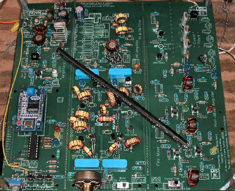
Section 1 - DDS VFO, DDS VFO amplifiers, and T/R SwitchThe left section of the board contains the DDS and DDS amplifiers.
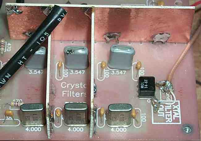
The output of the DDS VFO amplifiers is at the top left of the board and is marked inside a box "VFO Out" next to the 2N5109 transistor. The "VFO Out" is connected with a coax cable to the "VFO In", in the box at the lower right hand corner of the board. The "VFO In" is the input to the first mixer for the local oscillator (VFO). The T/R Switch is located above the 2N5109 amplifier and is from the W1FB QRP Notebook, Page 141. It uses the top half of the schematic with the PNP Switching circuit at the bottom. The switching from Receiver and Transmit is done at the outboard RF Amplifier that is added for more power to the BLT. The purpose of this switch is to send the DDS VFO output from the receiver to the outboard RF Transmitter. The output runs approximately 200mW. This level of output can drive almost any QRP transmitter. The Antenna input of the transceiver goes to the outboard transmitter switching circuit. Section 2 - RF amplifier and Input filtersThe middle section of the board contains the input filters and the RF amplifier. The "Antenna In" box is located in front of the two TV & FM yellow T50-6 toroids followed by the High Level RF Amplifier. The empty part of the board to the left of the TV & FM Filter is for an optional Broadcast Filter. The Bandpass Filters follow the RF amplifier and pass the signal to the First Mixer. The Bandpass Filters use varicaps and are tuned with a 25K to 100K panel mount potentiometer mounted at the Filter Tune holes. All the boxes with thin borders and thin lettering on the PCB are used if the boards are broken apart. The boxes with bold borders and bold lettering must be connected for receiver operation. Section 3 - First Mixer, Post-mixer amplifier, and Crystal FilterThe right section of board 1 contains the First Mixer, Post-mixer amplifier and the Crystal Filter. The mixer receives signals from the VFO section and the bandpass filters. The mixer and post-mixer combination has about 14 dB of gain. The mixer/amplifier signal is fed into the crystal filter threw a 2-LED switching circuit. The switching circuits uses two LEDs and one LED and one IRED. The IRED controls the output of the DDS amplifiers for even output from 40 to 10 meters. The design for the crystal filters follows the article "Designing and Building Simple Crystal Filters," by Wes Hayward, W7ZOI, QST, July 1987, P 24., where one value capacitor is used throughout the filter. The 3.457 MHz crystal filter needs 39pf capacitors for SSB listening. The second 3.547 MHz filter works best for CW with the 390pf caps for narrow bandwidth. The bandwidth of the crystal filters is varied by the value of the filter capacitors. A set of 200pf to 300pf capacitors will give you CW bandwidth, and 39pf capacitors will widen the bandwidth for SSB reception. The output of this section (at the upper right next to the T6-4T transformer) is the box labeled "Xtal Filter Out", with two soldering pads. The two pads are used to install a loop of wire for easy soldering and unsoldering during testing and building. The "Xtal Filter Out" is attached to the "Xtal Filter In" box at the Second Mixer on Board 2. Breaking up the BoardThis board can be broken into three sections along the through hole pads between the boards. Cut along the soldering pads on the bottom of the board with a utility knife. Cut several times and get into the board as deep as possible, then turn over the board and do the same thing. After several cuts on both sides, the sections should snap apart. If you feel you are using too much pressure to snap them apart, cut deeper into the board. Cutting the sections apart, shielding each one individually, using feed-through capacitors for 12 Volts, and using miniature coax for all connections will provide the cleanest receiver. IR Device Options The IR devices can be changed out with matched pair IR receiver/detectors mounted in a special case with a locking nut to hold 1000um fiber optic cable. The IR switching provides excellent RF isolation between the stages of the receiver. This pair of emitter/receiver and optic fiber is called the Experimenter's Kit IF- E10. It contains a matched pair emitter/detector as pictured above and 1 meter of 1000µm optical fiber. The IR Beginner's Kit cannot be used between the First Mixer and the First DDS amplifier. At this point I don't know what can be used to substitute for the present black tube and the IR devices now used. An IR Beginner's Kit can used between the 3.547 MHz Crystal Filter and the Crystal Oscillator on the second board. It is only used if you have two different crystal filters, i.e., one 3.547MHz and 4.000MHz. Otherwise, the Crystal Oscillator is locked onto the 4.000 MHz crystal that provides 455kHz output with the 3.547 MHz crystal filter from the Second Mixer/Crystal Filter. The two IR paths on the bandpass filters are not separated in the break up of the boards and they are not affected by ambient light levels (unless light is directly striking the diodes from a strong shop light or sunlight). When mounting the matched pair IR devices, put the C terminals in the same location. The A and E terminals are interchangeable, for example, an A terminal can go into an E terminal and vice-versa. Both of the IREDs at the crystal filters (in the special fiber optic connectors) will point to the center of the board, and the one at the crystal oscillator points off the board, pointing to the right. The "B" connection is ignored in the photo transistor footprints. Picture Using ShieldsIf you don't break the board apart, and want good isolation between the sections, put shields along the rows of through hole pads. Make the shields with PCB board about 1/2" to 1" high. In most cases this is all the isolation the board needs. Copper strips and tin strips 2" wide are sold at hardware stores. Make holes in the shields to let the IR energy pass through after carefully aiming and marking. |
|
The most important shields are the ones at the crystal filters, between the 455kHz IF strip and the BFO/Product Detector/Audio Amplifier strip, and the Second Mixer on Board 2. The number one problem which causes birdies in the receiver is DDS VFO energy and strong local broadcast stations being picked up by the Second Mixer. The Second Mixer is very sensitive. Shielding of the second mixer, by running wires through the holes surrounding the mixer, and soldering 1/2" to 1" copper or tin shields to the wires, will go a long way toward reducing birdies. Coax cable is essential between the "Xtal Filter Out" and the "Xtal Filter In" connections to keep the second mixer clean. |
|
TV & FM, BC Filters || RF Amplifier || Bandpass Filters || First Mixer & Amplifier || Crystal Filter
Send E-Mail || Amateur Radio Receivers || Blue Lightning Transceiver
