
|
RF isolation is improved considerably by using IR devices to switch circuits in the receiver. Most IR circuits use a modulated carrier to send commands, but this receiver uses unmodulated IR light. The circuits are very simple, and high output IR LED emitters make it work. |
|
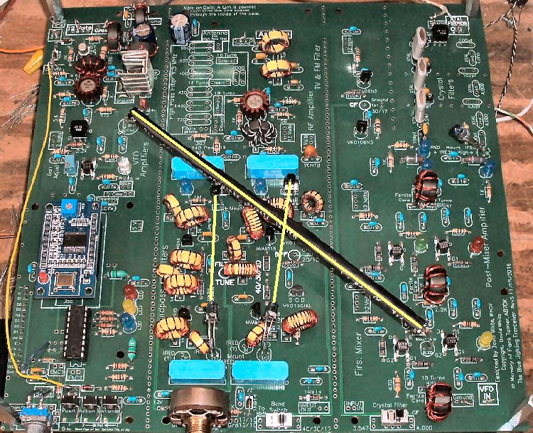
The yellow lines show the paths and places of all the IR devices. Click below on the links to find information on a particular IR path.
Bandpass Out || Bandpass In || Crystal Filter || Crystal Oscillator
All the IR (Infra-red) devices in this kit are used for simple switching. The basic operation is turning on an IR LED strong enough to saturate a phototransistor or photodiode, which raises the gate voltage of a MESFET to turn it on and activate a relay/LED. The IR LEDs (also termed IREDs)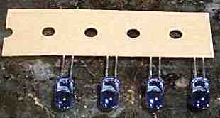 The IR LEDs are a Lite-On part number LTE-4208C. These IR emitters are high intensity Gallium Arsenide infrared emitting diodes mounted in clear plastic with a smoke color lens. They are made with Gallium Aluminum Arsenide window layer on Gallium Arsenide Infrared emitting diodes. Viewing angle is 20 degrees. Similar ones are used in BG Micro's "IR Illuminator Kit". They are Part No. LED1067 on page 8 of BG Micro's catalog. They have a clear lens and work in the kit as well as the LTE-4208C. You can order them with an email to BG Micro. Maximum current for the LTE-4208Cs is 50MA. The IR LEDs peak emission is at 940nm in the infra-red region of the light spectrum. Four IR LEDs are used in the kit, two at the bandpass filters, one at the crystal filter, and one at the First Mixer. IR ReceiversTwo types of IR receivers are used, a phototransistor and a photodiode. A silicon NPN Phototransistor, the BPX38-4, is located at the First VFO amplifier to control the Gate 2 bias, and at the crystal oscillator. A high speed photodiode, the PD410PI, is used at the input relays in the Bandpass Filters.  The BPX38-4 is a high sensitive silicon NPN epitaxial planar phototransistor in a standard TO-18 hermetically sealed metal case with a flat glass window. A base terminal is included with this phototransistor, but is not used in the kit's circuits. Use of the base does not increase sensitivity, but can be used as a sensitivity control, at some loss of sensitivity. Wavelength of peak sensitivity is 920nm, which matches fairly close to the IR LED, which has its peak emission at 940nm. The BPX38 phototransistor is a broad spectrum receiver, and is affected by wavelengths from 630 to 1040nm. Shop lights and sunlight can turn it on. The collector current of this phototransistor is 50mA, so it can drive a relay by itself. However, the amount of infra-red hitting the lens has to pretty intense to get this current flow. The advantage of this high collector current is that with high impedance gate devices (MOSFET, MESFETs, & similar devices), it does not take much IR energy to raise the gate voltage to turn on the device. With the IR LED supplied with the kit, distances of 8" are easily obtainable in low ambient light levels without having to tube the path, with gate resistors of only 47K to 100K.  If the paths are covered, much longer distances can be obtained with impedance levels of 100K or above. The impedance levels used in the kit are 47K and 100K, and provide plenty of sensitivity to work at 6" to 8". Impedance levels of 1 Meg and above make the device so sensitive that it is hard to control when used in an uncovered path. When the path is covered, with a black tube, the distance can be increased substantially. 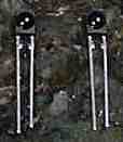 The other IR receiver used is a photodiode, a PD410PI. This part is available from BG Micro (page 7 of their catalog). Their part number is DIOPD410PI. This is a high speed (200ns) photodiode with a peak sensitivity at 1000nm. The peak output of the IR LED is at 940nm, but the diode's sensitivity at 940nm is only 10% down off its peak, so they work well together. The diode is only sensitive in the infrared region, from 850 to 1150nm, so shop lights do not affect them as much as the phototransistor. The top 10% sensitivity range is 940 to 1030nm. The diode has a built in visible light cut-off filter, the reason for its dark color. The diode was mainly designed for infrared remote controllers. Remote controls add another plastic filter in front of the photodiode.  A photodiode is put into a circuit backwards (cathode towards 12 Volt side of circuit), blocking a current from flowing through it. Infrared striking the photodiode lets current flow through the device. A impedance of 1 Meg was determined to be the best value to use in ambient light. With the 1 Meg impedance, the longest distance it would work was a little under 4". The phototransistor had better sensitivity at long distances - about 8" at the most. The impedance levels with the phototransistor are between 47K and 100K, whereas a photodiode at the same distance required several megohms. The power capability of the diode is much less than a phototransistor. You can source very little current through the diode (.1mA at most). I was never able to turn anything on with the diode, except the gate of a MOSFET/MESFET, or a high impedance FET, with a high value gate to ground resistor - 1 meg in this receiver. Photodiodes are the choice for long range communication in 40KHz communications, i.e., remote controls. The photodiode is set up in a high impedance circuit, and the remote controls are pulsed at a very high current to activate the photodiodes. However, in a non-pulsed system, like the one in this receiver, the phototransistor beats the diode in long distance communication. That is why the longest paths on the board are using phototransistors. You can make the photodiodes work at the same distance as the phototransistors, but the paths must be covered or they will turn on too easily with ambient light levels. |
|
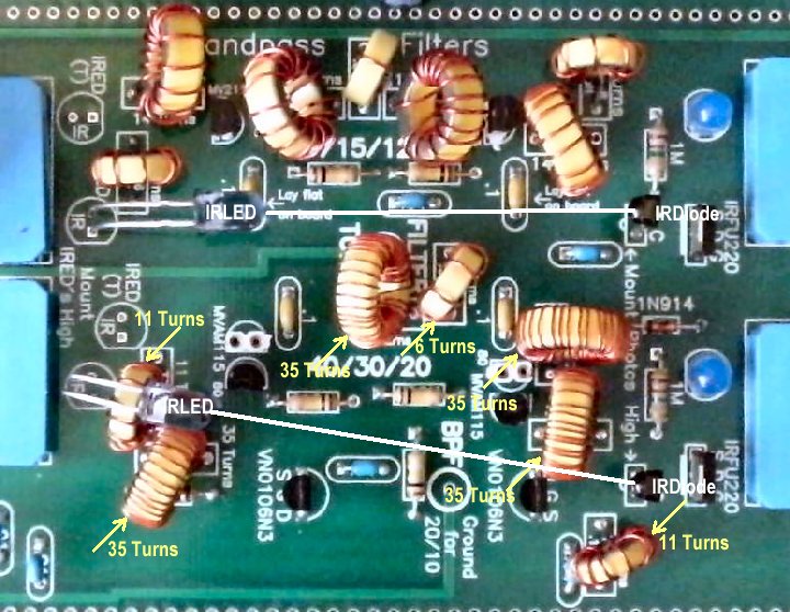
The IR LEDs in the Bandpass Filter circuits are in the ground circuit of the relays. The IR LEDs are current limited to 10 to 15 MA by the 500 ohm coil resistance of the relays and by the losses of the switching MESFETs (VN0106N3). The switching circuit uses two VN0106N3s and is located at the bottom of the image above. All the IR photodiodes are used around the Bandpass circuit. In the image above, the two photodiodes on the right control the bandpass input relays. The photodiodes turn on IRFU220s, located behind the photodiodes, which turn on the relays. |

|
The crystal filter uses three LEDs (either Super Bright or regular) and one IR LED. They switch the bandpass filters.
The crystal filter uses one IR LED, turned on by the switching circuit, located at the top of the above image, similar to the one used at the bandpass filters. The crystal filter LEDs and the IR LED use a 470 ohm resistor to limit the current to 20ma. The 470 ohm resistors can be replaced by 220 ohm resistors to raise the IR output of the IR LED, but this increases filter loss slightly. The crystal filter LEDs are in the signal path of the crystal filters. Even though the IR LED is used with long leads and bent over to aim at the IR receiver, no problem has been found with RF passing between the leads. First, using 20MA to drive them, the RF signal is just not strong enough to effect that much current. In Daniel Wissell's "The OCR Receiver", June 1998 QST, pp35-38, the current set through his diode (part of an optocoupler) to let the RF modulate it is in the microamps. Secondly, this IR LED is not responsive to the 3 to 4 MHz frequencies. There aren't even any specs on the data sheet regarding frequency response. |

|
The image shows the location of the phototransistor at the crystal oscillator. This oscillator is on the second (top) board of the set. If the boards are stacked with this one on top, the phototransistor is mounted upside down on the board to hit the IR LED shooting up from the 4.000 MHz crystal filter, as shown in this image. |

|
It is important to cover the path with a black tube, as strong ambient light levels will partially turn on the 3.547 crystal, giving a loud howl out of the receiver speaker. If the light fully turns on the 3.547 crystal, there will be no signals on the band. |

Commercial Pairs w/1000µm Optical Fiber Blue - IRED Emitter || Black - Phototransistor Receiver This pair of emitter/receiver and optic fiber is called the Experimenter's Kit IF-E10 in the Fiber Optics Kit section of Industrial Fiber Optics, Experimenter's Kit IF E10 web site. It contains a matched pair emitter/detector as pictured above and 1 meter of 1000µm optical fiber. However, these sets do not work with the 1st Mixer to 1st VFO Amplifier path in the BLT. With the BLT, if you mount Board 1 and Board 2 where the IR LED at the 4 MHz crystal filter (Board 1) can't see the Phototransistor at the crystal oscillator (Board 2), then one kit will be needed. Connecting the commercial pairs to the PCB footprints is easy. Note that the "C" terminals of both devices are placed in the same hole. The "E" terminals of the phototransistors are interchangeable with the "A" terminals of photodiodes. The "B" terminal can be ignored on the footprints for the phototransistors. Be sure to get the right color device in the right place. The Black colored holder is the phototransistor and the Blue colored holder is the IR Emitter. |
Send E-Mail || Amateur Radio Receivers || Blue Lightning Transceiver
