
|
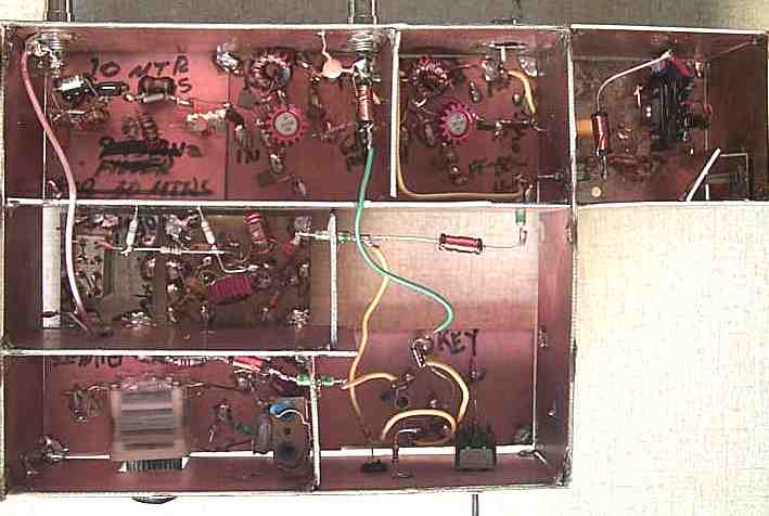
This part of the project includes everything except the VFO amplifiers and low pass filter (located in receiver), and the output filter for the final amplifier. |
|
Input is at the left where the .01 capacitor is across the left side of the image. The circuits were take off a prototype board of the Electroluminescent Receiver, which were done "surface mount" style. Output is at the right where "out" is written on the board. This board is located in the receiver, and is completely shielded. The "out" connects to an RCA phono jack at the back of the receiver. Then a cable is run to the transmitter mixer "RF" input. |
|
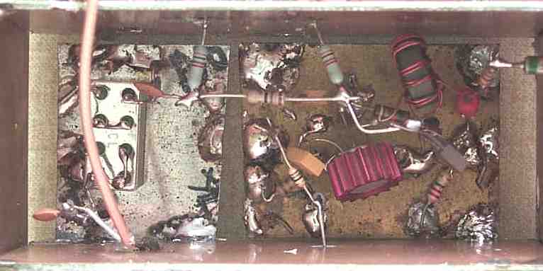
RF Chokes and feedthrough capacitors were used throughout the project to keep the 12 Volt line clean. 12 Volts for the circuit is the connection to the RF Choke. The feedthrough cap on the bottom left is 12 Volts to the VXO. |
|
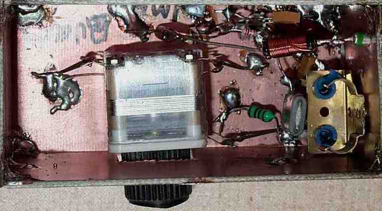
The capacitor is a miniature broadcast variable, probably about 200pf. Keyed 12 Volts comes through the feedthrough cap connected to the RF Choke. Output is at the top middle of the board, to the left of the upside down metal case 2N2222. |
|
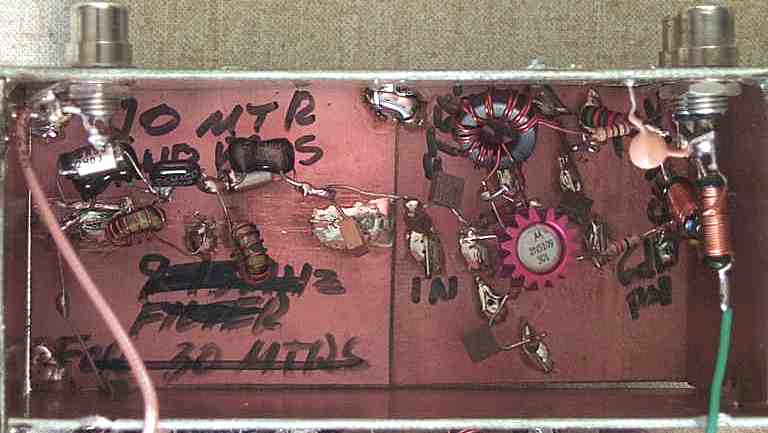
The 2N5109 amplifier on the right is the VXO amplifier. Input to the amp is at the bottom middle. Output of the amplifier connects to the 3dB resistive pad. The 3dB pad is soldered on the side of the shield at the top and connects to the "LO" input of the mixer. The cable coming across the left of the image is the input from the VFO and amplifiers from the receiver. It is hiding the output to the bandpass filter, which is at the top of the image right above the upper left hand corner of the mixer. |
|
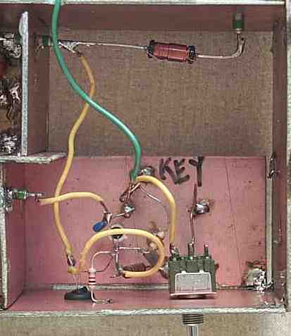
Input to the bandpass filter from the mixer is at the bottom left. The RCA phono jack at the top left is the VFO from the receiver. The phono jack at the top right is 12 Volts to the circuit. The jack at the bottom is the optional output from the first output amplifier. The output of the amplifier is hidden under the RF Choke, and goes to the second 2N5109 output amplifier chain. |
Send E-Mail || Amateur Radio Receivers || CW Transmitter w/Superhet Receivers