|
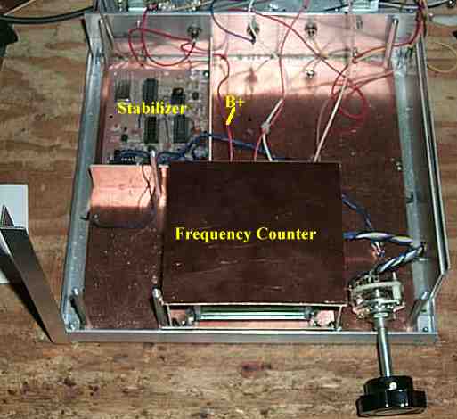
The picture shows a suggested place for the frequency counter. Note that the whole counter is surrounded by double sided PCB material. The pieces are soldered together at the corners.
There is no need to completely solder all along the edges, as any space smaller than 1/8" will be unlikely to leak RF at the frequencies of the receiver.
The frequency counter shown here was set up to use a rotary switch, and that is why it is shown with wires entering the box on the right side.
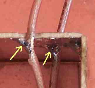
Soldering the Cable Shields to the Inside of the BoxThese two miniature coax cables carry the signals from the VFO and the Crystal Oscillator.
The insulation is carefully removed from the cables where they leave the shield box and are soldered to the inside of the box. This soldering keeps ground loops from occuring between the counter and the receiver.
The easiest place to find a good place to solder a wire to the PCB was in the upper left hand corner. A bare wire was soldered to the PCB and then to the shield box.
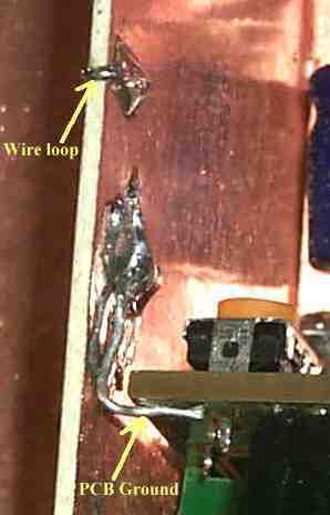
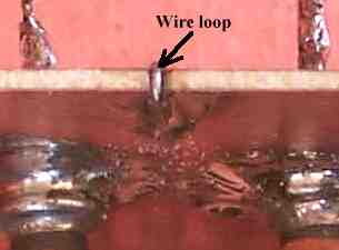
Soldering Loops on the sides of the PCB BoxA small file was used to make a groove on the top of a side piece and then a small wire loop was placed over the PCB material and soldered on both sides. This makes sure that every part of the shield box is properly grounded.
|