
|
Since the Electroluminescent Receiver is so unusual, with its 21 LEDs and Infrared switching, finding an acceptable box is difficult. If a metal box is used, the LED display is hidden, and metal boxes are priced too high for most homebrewers. Some plastic boxes come in clear plastic, but they are so rare the size found is not large enough. And the same problem happens with a black plastic box as a metal box, the LED display is hidden. A clear homebrew clear acrylic box is the best way to go, but unfortunately, if used for ham communication with a transmitter, doesn't resolve the shielding issue. For QRP operation, the shielding is not needed, but for QRO operators, shielding is almost a necessity. On this page will be listed some ideas for cases, and will be expanded as more ideas come to fruition. Instructions for an easily constructed, clear acrylic box is being worked on, but for now, the DM-3 box will be presented to help with ideas for those that would like to build a case, or even use the DM-3. |
|
The first inexpensive box found for the kit was a DM-3 made by Pac Tec. Pac Tec enclosures are handled by Fry Electronics and can be purchased from them if one is in your area. The case external dimensions are 11.4 X 10.4 X 3.3 inches. The PCB dimensions are 10.9 X 9.9 X 3.3 inches. The Kit's PCB dimensions are 8.5 X 8.5 inches, so it fits inside the box with plenty of room to spare. This information is mainly to show how the boards can be mounted in a box and spur some ideas to inspire your own design. 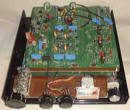 Board 1 is placed on top, then a PCB shield, and Board 2 on bottom. The placement worked out since all the connectors for the front panel controls and outputs at the back were convenient. |
|
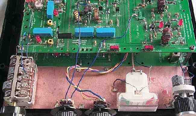
A PCB board was cut and screwed to the front of the case for easy mounting of the front panel controls and S-Meter. The main tuning capacitor is soldered to the front PCB piece for a sturdy mount. The wires to Board 1, where the VFO is located, need to be larger than in the photograph to promote stability. The #22 hookup wire used in the prototype vibrated too easily. Don't forget a ground wire from the main tuning and BFO cap to the Kit's PCB ground. The bandpass and crystal filter switches have been left on the board, but for operator convenience, they need to be moved to the front panel. Simple panel mount SPST switches are all that is needed, unless the DFD2 frequency counter is used, then SPDT switches are used. All the controls/switches, except the main tuning cap, can be mounted on the plastic front cover. If a frequency counter is included, there is plenty of room above the Bandpass and Audio pot (or S-Meter) to cut a slot for the AADE DFD2 frequency counter. |
|
In this prototype, all the controls were soldered to the PCB board. The S-Meter was glued. The BFO cap is soldered to a stack of two spacers, then the spacers soldered to the PCB. The backs of the pots were scraped to clean the back, then soldered to the PCB. A lot of solder is needed to make a sturdy mount.
Soldering the backs of the pots to the PCB has not worked very well. All the controls other than the main tuning cap would best be mounted on the front plastic cover. If a clear front cover is fabricated, the LEDs on the IF strip can be seen flashing though the front. |
|
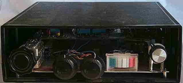
The back shows phono plugs soldered to the ground plane of the PCB boards. Panel mount connectors on the back cover would be best. These boards are typical of mistakes made in the initial stages of prototyping a project, the traces were put on backwards putting the ground plane and traces on the top of the board. The board was soldered "surface mount" style to work. The middle top connector is the antenna connector. A regular coax connector mounted on the back panel would be best. The bottom left is the speaker connector. The audio amp heat sink can be seen just behind the connector. The power supply connector for 12 volts is at the upper right. A different connector than the one for the speaker should be used, to keep from accidentally putting power into the speaker connection. The coax off the 12 volts connector supplies 12 Volts to the bottom board, shown soldered at the lower back middle of Board 2. A commercial pair of IR emitter/phototransistors are used. Only one is needed between the left side of the crystal filter and the crystal oscillator (bottom board on the right). The optic cable that goes from the right of the crystal filter to the VFO amplifiers is not needed and can be replaced with black tubing. |
|
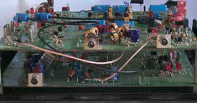
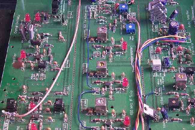
The connections to the bottom board are shown above. The audio pot connections are at the upper right, the S-Meter is to the left of the audio amp heat sink. The AGC connections in the IF strip are in the middle of the board. The coax on the left comes from Board 1 "XTAL FILTER OUT " square, to the "XTAL FILTER IN" square shown on Board 2 at the bottom left. |
Send E-Mail || Amateur Radio Receivers || Electroluminescent Receiver