
|
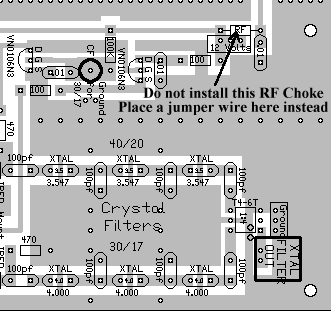
>Put the .01 capacitors in first. There are 95 of these. The values are inside the footprint for easy identification and the edges of the footprint are rounded. Remember, all the rectangle footprints that are rounded indicate capacitors, those that are squared off indicate footprints for resistors. >Put in the 28 100 ohm resistors next. The values are inside the footprint. Remember, square edges for resistors, there are some 100pf capacitors that go on the board, but the values are on the outside of the footprint and the edges are rounded. >Then put in the 32 100K resistors. The values are inside the footprint. Keep in mind which ones your are putting in so you don't put a 100K where a 100 ohm goes, and vice-versa. The 100K's are easy to spot because of the bright yellow band on one end. Do not go nuts over finding every single footprint for the above parts. Put in as many as you see, and then put the others in (as you find them) when you populate the board with the other parts. >The rectangular footprint with square edges that has "RF" inside the footprint are for the 250uH RF chokes. Note that there are two footprints for "Large RF", those are for the large wirewound chokes in the same bag as the smaller ones. Note: There was an error made on the board concerning the RF Choke next to the "12 Volt" box above the VN0106N3 switching circuitry on Board 1 next to the Crystal Filters. Do not install that RF Choke. Install a jumper wire instead. See the picture below:  Installation of this choke will cause the First Mixer to oscillate.
>Go through the bags in the following order: Bag 3 - parts with 10 or more pieces (includes the .01's, 100K's, RF Chokes, & 100 ohm's)
Use the Parts List to locate where the parts go on the boards. The relay pins are very fragile, be very careful. Do not bend the relay pins when inserting into the board. Look for silkscreen instructions and when in doubt, look at the pictures on this website. Because of its weight and size, leave mounting the tuning capacitor for the VFO last. >All the squares and circles with BOLD lines indicate connections (more details here) that must be made and are the following: >All connections (more details here) to off-board components are also squares with BOLD lines and are the following: The squares with thin lines, that do not indicate parts, are used only if you split up the boards. They can also be used for testing or tying into modifications. >See Mounting/Testing Board 1 and Mounting/Testing Board 2 to finish the receiver. |
Please Be Careful - Static Sensitive Devices!The most important thought that must be kept in mind is that 90% of the active devices are static sensitive parts. There are two areas of precaution that should be taken to ensure that you build the receiver without problems. First, if you walk across the floor of your work room and get a static discharge when you touch the door knob to your work room, have a ground lead handy to give a quick touch when sitting down to work. The highest risk factors are living in a very dry environment (or a day with very low humidity), wearing rubber sole shoes, and carpet on the floor. Second, check the ground on your soldering gun by putting an LED between the tip of the soldering gun (when turned on) and the ground you are using. Polarity does not matter nor do you need a resistor in series with the LED. If it lights, you do not have your soldering iron grounded properly. This situation is most likely to occur in two wire electrical systems, where there is no third ground wire (two prongs only). The receiver is most susceptible to the above problem after it is built and connected to an antenna that has a proper ground. When soldering on the board, using an improperly grounded soldering gun will blow an active device, even if you got away with it earlier. The soldering gun will put 120VAC (or 230VAC) on the trace you solder and travel to the ground of your antenna. |
|
|
Send E-Mail || Amateur Radio Receivers || Electroluminescent Receiver || Back to Instructions for the Kit
