
|
This procedure will help you make sure you have the band frequencies correct. The frequencies used to set up the receiver for CW will be used, the SSB frequencies will be noted in ( ) parenthesizes next to the CW ones. The normal bandwidth of the main tuning control is about 150 kHz, which allows receiving CW or SSB (on 40 and 20 meters), but not both at the same time. This allows for easy tuning of the signals with the large knob in the kit mounted on the main tuning capacitor. To receive both CW and SSB (on 40 and 20 meters) a reduction drive will be needed so you will have an easier time of tuning in signals. A small CDROM will fit with the tuning capacitor. See "Small CDROM Used for a Reduction Drive" for instructions or ideas on what might work for a homebrew option. There are plenty of commercial reduction drives available from surplus electronic stores or at Amateur Radio hamfests. Shaft size of the main tuning capacitor is 1/4". Secondly, the tuning range will need to be expanded to 300 kHz to include the entire 20 and 40 Meter bands. Instructions for changing the bandwidth of the tuning range will be noted later. Please note: Have the main tuning capactor fully closed - plates on the capacitor fully meshed - for all the tests that follow on all bands! |
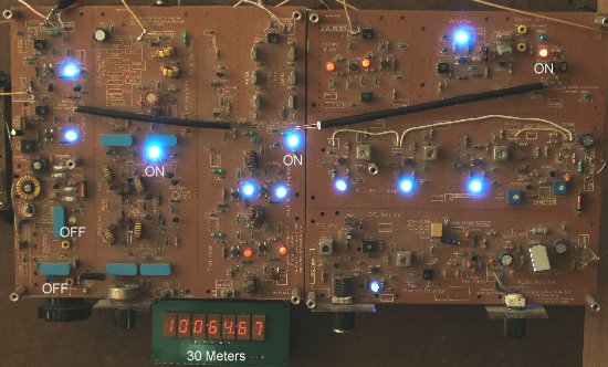
30 MetersThe frequency shown on the Frequency Counter will be 10.065 MHz with the tuning capacitor fully closed. The band ranges from 10.100 MHz to 10.150 MHz and is CW only. Most activity is at the lower portion of the band - 10.100 MHz to 10.125 MHz. Set the band switches as shown below: 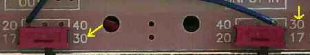 A VFO frequency of 14.065 MHz is used for both 30 and 17 meters. Since 17 meters starts at 18.068, the 30 Meter frequency will start at 10.065 to accommodate the starting point of the 17 Meter band. If you need to check your VFO frequency for this band before going through this diagnosis, jump to Checking the VFO Frequency first and make sure the VFO is set correctly. Be sure the band swiches are set to 30 meters. Note: The Frequency Counter does not have a decimal point between the MHz (megahertz) and kHz (kilohertz) ranges, i.e., the counter shows 10065.00 MHz for what will be shown on this page as 10.065 MHz. The .00 on the counter is the Hertz range, showing the 100 Hertz and 10 Hertz values. Accuracy to the kHz value will be sufficient for setting up the bands, i.e., with 10065.00 MHz, the kHz value is the 5. The following LEDs will be ON with the 30 Meter position on Board
1: >Both LEDs at the VFO will be OFF. >On Board 2, the 3.547 MHz crystal LED will be ON. |
|
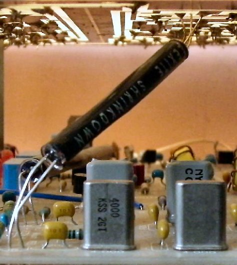
On both 30 and 17 meters the 4.000 MHz Crystal Filter IR LED is ON along with the 30/17 Crystal Filter LED. If the 3.547 MHz crystal LED is not ON at the Crystal Oscillator on Board 2, one problem could be that the black tubing is bent, or missing, not allowing the IR light from the Crystal Filter from reaching the Phototransistor at the Crystal Oscillator. Make sure the tubing is straight or move it slightly to see if the LEDs at the Crystal Oscillator switch. Board 1 and Board 2 are shown side-by-side on this page, but for the recomended build of Board 2 over Board 1, see the picture below showing the black tuning between the Crystal Filter and the Crystal Oscillator. Forgetting to install the black tubing is a common mistake when mounting Board 2 causing improper operation of the Crystal Oscillator switching. |
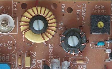 Adjust the 2/8 Ceramic Capacitor seen in the upper left of the above picture to set the frequency readout at the Frequency Counter to 10.065 MHz (to allow for some room at the lower band edge). If you are having trouble getting the correct frequency, i.e., the Frequency Counter is showing a reading about 400 kHz off (shows 10.500 MHz or similar high value), turn the receiver OFF (disconnect 12V from the receiver) and then back ON to reset the Frequency Counter. Carefully watch the Frequency Counter: 1. The decimal point should come on for about 1 second. If 4.000.00 does not show, but 3.546 (within a kHz or any value in the 3 MHz range) does, the Frequency Counter is not picking up the correct offset from the Crystal Oscillator on Board 2. Go to the Frequency Counter instructions (Crystal Oscillator Modifications and Crystal Oscillator Connections) and make sure all the connections are correct between the Frequency Counter and the Crystal Oscillator on Board 2. Checking the VFO FrequencyTo check the VFO frequency, ground the "Freq Cntr" box connection to Ground at the Crystal Oscillator on Board 2. Then turn the receiver OFF and then back ON to reset the Frequency Counter. 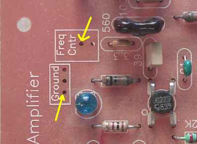 Carefully watch the Frequency Counter: 1. The decimal point should come on for about 1 second. If Step 2 does not show 0.00 MHz, check your ground at the "Freq Cntr" box. If using a chip lead, the ground should be close to the "Freq Cntr" box or the counter could show an offset of 50 Hz to several kHz. Then turn the receiver OFF and then back ON to reset the Frequency Counter. 17 MetersThe frequency shown on the Frequency Counter will be 18.065 MHz with the tuning capacitor fully closed. The band ranges from 18.068 MHz to 18.168 MHz. 18.068 to 18.110 is used for CW and 18.110 to 18.168 is used for SSB. The whole band is covered with the main tuning capacitor so both CW and SSB can be heard with no modifications. When 30 Meters has been set up properly, switch the receiver to 17 Meters. The picture below shows the correct positions: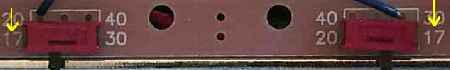 The following LEDs will be ON with the 17 Meter position on Board 1: >Both LEDs at the VFO will be OFF. >On Board 2, the 3.547 MHz crystal LED will be ON. |
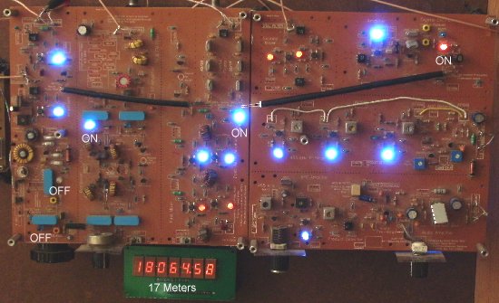
| As shown above, the Frequency Counter should show 18.065 MHz (within 1 to 2 kHz). If the 30 Meter band was set up properly, there should be no problem with 17 Meters showing the above frequency (within 1 to 2 kHz). |
|
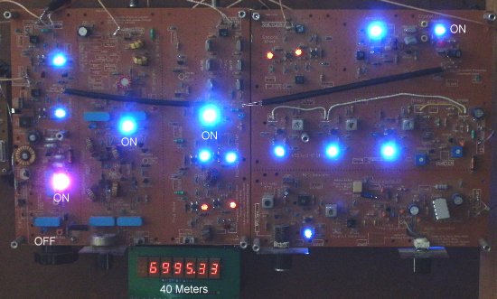
40 Meters will show 6995 MHz with the tuning capacitor fully closed. 7.000 MHz to 7.125 MHz is the CW section, and 7.125 MHz to 7.300 MHz is the SSB section. Since the stock tuning range with the main tuning capacitor is only 150 MHz, you can receive either the CW or the SSB section, but not both, without making modifications.
To allow for some room on the low band edge, the frequency on the Frequency Counter will show 6995.00 MHz.
Set the band switches as shown below:  Checking the VFO FrequencyTo check the VFO frequency, ground the "Freq Cntr" box connection to Ground at the Crystal Oscillator on Board 2. Then turn the receiver OFF and then back ON to reset the Frequency Counter. Carefully watch the Frequency Counter: 1. The decimal point should come on for about 1 second. If Step 2 does not show 0.00 MHz, check your ground at the "Freq Cntr" box. Then turn the receiver OFF and then back ON to reset the Frequency Counter. Adjust the 10.545 yellow trimmer, if needed, to 10.542 MHz. The following LEDs will be ON with the 40 Meter position on Board 1: >One LED at the VFO will be ON at the 10.545 relay. >On Board 2, the 4.000 MHz crystal LED will be ON. |
|
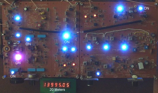
If you have trouble getting the correct frequency on the Frequency Counter, turn the receiver OFF and then back ON to reset the Frequency Counter. (Take the ground off the Crystal Oscillator "Freq Cntr" box first.)) Carefully watch the Frequency Counter: 1. The decimal point should come on for about 1 second. If 3546.00 does not show, but 4.000 (within a kHz or any value in the 4 MHz range) does, the Frequency Counter is not picking up the correct offset from the Crystal Oscillator on Board 2. Go to the Frequency Counter instructions (Crystal Oscillator Modifications and Crystal Oscillator Connections) and make sure all the connections are correct between the Frequency Counter and the Crystal Oscillator on Board 2. If you have the Crystal Oscillator switching working correctly with 30/17 Meters, you should not have any problem with the switching on 40/20 Meters. If light is leaking into the Phototransistor through the back (where the leads are) of the Phototransistor from a bright light, it could cause the Phototransistor to turn ON. You can test that with your finger over the back blocking any light. The Phototransistor is OFF when receiving 40/20 Meters - no light entering the Phototransistor. After fixing the problem, reset the receiver (turn OFF, back ON) and check the frequencies on the Frequency Counter. Third, Check 20 Meters20 Meters will show 13.995 MHz with the tuning capacitor fully closed. 14.000 MHz to 14.150 MHz is the CW section, and 14.150 MHz to 14.350 MHz is the SSB section. Since the stock tuning range with the main tuning capacitor is only 150 MHz, you can receive either the CW or the SSB section, but not both, without making modifications. To allow for some room on the low band edge, the frequency on the Frequency Counter will show 13.995.00 MHz. Set the band switches as shown below: 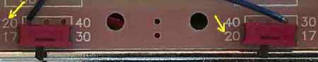 Checking the VFO FrequencyTo check the VFO frequency, ground the "Freq Cntr" box connection to Ground at the Crystal Oscillator on Board 2. Then turn the receiver OFF and then back ON to reset the Frequency Counter. Carefully watch the Frequency Counter: 1. The decimal point should come on for about 1 second. If Step 2 does not show 0.00 MHz, check your ground at the "Freq Cntr" box. Then turn the receiver OFF and then back ON to reset the Frequency Counter. Adjust the 10.455 yellow trimmer, if needed, to 10.450 MHz.The following LEDs will be ON with the 20 Meter position on Board 1. >Both LEDs at the VFO will be ON at the 10.545 relay and the 10.455 relay. >On Board 2, the 4.000 MHz crystal LED will be ON. |
|
If you have trouble getting the correct frequency on the Frequency Counter, turn the receiver OFF and then back ON to reset the Frequency Counter. (Take the ground off the Crystal Oscillator "Freq Cntr" box first.)) Carefully watch the Frequency Counter: 1. The decimal point should come on for about 1 second. If 3546.00 does not show, but 4.000 (within a kHz or any value in the 4 MHz range) does, the Frequency Counter is not picking up the correct offset from the Crystal Oscillator on Board 2. Go to the Frequency Counter instructions (Crystal Oscillator Modifications and Crystal Oscillator Connections) and make sure all the connections are correct between the Frequency Counter and the Crystal Oscillator on Board 2. If you have the Crystal Oscillator switching working correctly with 30/17 Meters, you should not have any problem with the switching on 40/20 Meters. After fixing the problem, reset the receiver (turn OFF, back ON) and check the frequencies on the Frequency Counter. SSB Modifications for 40/20 MetersVFO Modifications with the Frequency StabilizerThere are no capacitor changes with the frequency stabilizer. The changes already made when installing the stabilizer will reach the required VFO frequencies. Set the VFO frequencies for the 10.545 relay and 10.455 relay as follows: ____The frequency with the 10.545 relay (40 meter SSB, one LED on) is 7.125 MHz (VFO is 10.695 MHz). Make sure the main tuning capacitor is all the way closed. Set the frequency using the 10.545 yellow trim capacitor. Frequency should range from 7.125 MHz (VFO 10.697) to 7.393 MHZ (VFO 10.955 MHz). The top of the band is 7.300 MHz (VFO 10.847 MHz), so almost the whole band could be covered by setting the frequency with the tuning cap all the way open to 7.300 MHz (VFO 10.847 MHz). The first 60 kHz of the band would not be received. ____The frequency with the 10.455 relay (20 meter SSB, both LEDs on) is 14.150 MHz (VFO 10.605 MHz). The tuning capacitor is all the way closed. Set the frequency using the 10.455 yellow trim capacitor. Frequency should range from 14.150 MHZ (VFO 10.605 MHz) to 14.395 MHz (VFO 10.850 MHz). |
Send E-Mail || Amateur Radio Receivers || Electroluminescent Receiver || Back to Ham Radio Instructions