
|
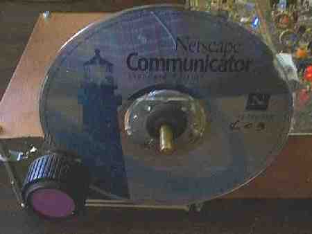
The most difficult part of this operation is determining what CD ROM to use. Your favorite CD, a junk one that is useless (but doesn't look good), the kit CD ROM (kinda boring), or the ARRL Designer CD ROM? By being very careful, the CD ROM should not be damaged used in this manner. And which side? You can certainly have a shimmering appearance using the other side than shown in the pictures. A "special effects" CD-ROM can be made with a Microwave oven. A Microwave oven makes a fractal pattern that gives some very interesting results. Plus a lot of fun, especially trying to do it without getting caught. Picture A Tesla coil produces spectacular results, which is totally appropriate for the Tesla VFO design. This is a must see site at "CD Zapping" at http://www.electricstuff.co.uk/cdzap.html After this operation, the VFO will suck in signals like you could never believe! Picture |
|
Three rubber grommets are used to hold the CD ROM onto the shaft of the tuning capacitor. A 5/8" rubber grommet is put inside the hole of the CD ROM first. Then two 3/8" rubber grommets are pressed inside the 5/8" grommet from each side. The 3/8" grommets will go in a little more than halfway, leaving the outside half showing on each side. This gives a very tight fit, and the two grommets in the middle provide a lot of stability for the CD ROM. Take the CD ROM to the hardware store when purchasing the grommets, as the dimensions are not always marked the same as the ones above. If the capacitor shaft is notched at the end, purchase a 1/4" wooden dowel stick, and split a short piece in half, and use it to round out the end so the grommets will be centered on the shaft when installed. |
|
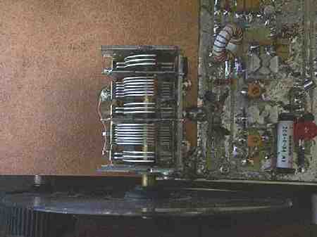
This picture shows the back side of the CD ROM and the backside grommet halfway inside the 5/8" grommet. This picture also shows how the prototypes were made. The traces were put on the top side of the PCB, and the parts soldered to the traces. This prototype was before the hole on the PCB was made to hold the toroid, with air variable trimmers, and an early style relay. |
|
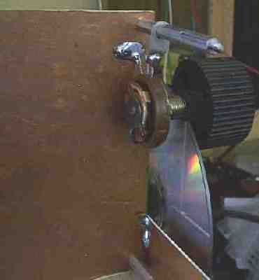
A junk box potentiometer is modified as a reduction drive. The back is taken off to remove the stop indentation. Now the pot can turn freely. Then a 3/8" rubber grommet is put over the shaft of the pot. The pot is mounted so that there is a fair amount of pressure against the CD ROM, so that it can turn the CD ROM without slipping. The slot in the outside diameter of the grommet makes a perfect place for the CD ROM to fit. Too much pressure will cause as many problems as too little pressure. In the picture, the pot was soldered to a soldering lug on the spacers, then the tension was effected by pushing against the CD ROM, and soldering the other lug to the ground plane. There are many variations on how this can be done. The illustrations above should give you the basics on how to do the operation in your special situation. |
Send E-Mail || Amateur Radio Receivers || Electroluminescent Receiver || VFO || Back to Receiver Range and SWL Information
