VFO Fine Tuning
To change the VFO frequency, either change the value of C35 or add turns (lowers frequency) or remove turns (raises frequency) from the VFO toroid. The tap does not need to be changed for minor changes. Remove or add turns at the top (left side on schematic) of the coil.
VFO maximum frequency range is 3 to 10 MHz for this board. Experimentation is encouraged outside this range. Lower frequencies should be no problem. Higher frequencies are limited by the lead lengths on the board and layout.
C32, C35, and C30 are used to tune the frequency of the VFO.
For VFO's in the 3 or 4 MHz range that are used for 40 and 20 meter reception, greater VFO range is obtained by connecting the stator of the 35pf tuning capacitor to the VFO side of L2, marked "WIDE" on the silkscreen.
In every case, a small tuning range is obtained by connecting the stator to the "VAR CAP" pad, and a large tuning range by connecting the stator to the VFO side of L2, marked "WIDE" on the silkscreen.
If a general coverage receiver is used to set the VFO frequency, place a short antenna lead near the VFO and tune the receiver for a signal. Adjust C32 to put the VFO on the proper frequency.
If a signal generator is used, place a short lead from the output of the generator close to the receiver. Tune C32 until the signal is found.
The output of a crystal oscillator can also be used to generate a calibration signal. For setting up a 20 meter receiver, set the generator at 14 MHz and tune C32 with the VFO tuning capacitor (35pf panel mount) closed. For setting up an 80 meter receiver, set the generator at 3.5 MHz and tune C32 with the VFO tuning capacitor open.
The circuit board is also drilled at L2 so that a shielded coil similar to the TOKO transformer can be used. Shielded coils used for 10.7 MHz IF's can be used for VFO's in the 5-10 MHz range.
This layout also accepts the L46 series of Amidon shielded coils. The L46-6 is recommended. The 85pf trimmer can be removed or replaced with a fixed value, since the slug in the coil can be used to set the frequency. Additionly, both the 85pf trimmer and the slug in the coil could be used to set the frequency also.
If no test equipment is available, turn the trimmer at C32 a little bit at a time while peaking the "ANT ADJ" trimmer. Your tuning capacitor should be connected to the wide range pad. Tune the VFO tuning capacitor and listen to the signals. When you
hear some familiar signals, you will be close to the band your looking for. Ham radio communication is unique, and should be easily picked out.
Only four capacitors are needed to vary the oscillator from 3 to 6 MHz. Change coil size and a range from 6 to 10 MHz can be covered with the same capacitors. See chart in Step 6.
Varactor Tuned VFO
An alternative to finding and mounting a venier drive for the tuning capacitor, this VVC tuned circuit can make life easier. The 2N3904 is used as a temperature compensation diode for the VVC diodes.
The MV2109, MV2104 or similiar diodes are recommended. Best to build the circuit underneath the board directly to the ground plane near the VFO circuit. Use one tuning diode (MV2), R1, and C1 as stand-offs (one end soldered to ground) to mount the transistor
and choke. The other tuning diode connects to the "WIDE" copper pad.
R2 is used as a current limiter to protect the transistor and diodes. R2 can be raised in value, but do not lower the value. R3 can be changed to any value.
The diodes will add about 10 to 20pf to the VFO circuit. To compensate, lower the value of C35 10 to 30pf and recalibrate your VFO frequency.
Winding the Coils
This step gives instructions for winding the two coils for the kit, the input coil and the VFO coil.
Both coils use a T80-6 toroid supplied with the kit. Wire size is not critical. Larger sizes (#22 - #24) are easier to handle. Sizes #20 to #28 will work.
The input coil has two windings. The primary is wound first (Part A). Then the secondary is wound over the primary (Part B).
The VFO coil has one winding with a tap. Instructions are in Part C.
A. Input Toroid - Primary Winding
Cap Across C2 - Place across C2 on copper side of board. Install when placing the toroid on the board.
Mark the primary wires with a piece of tape so they will not be confused with the secondary winding.
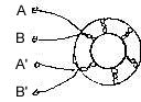
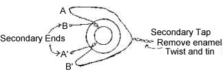
B. Input Toroid - Secondary Winding
Wind 10 bifilar turns over the primary winding - same for all the bands.
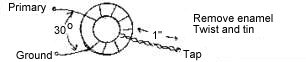
1. Take two wires, 12 inches long
2. Twist the two wires together leaving 1" leads at each end.
3. Wind twisted pair over the primary - 10 turns
4. Trim extra lead length. Scrape the enamel from the ends (about one inch) with fine sandpaper, knife or razor blade.
5. Connect A to B', this is your secondary tap.
Then B and A' are your secondary ends.
C. Wind VFO Toroid
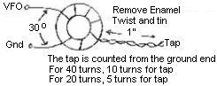
Tap for 40 Turns, 10 Turns
Tap for 20 Turns, 5 Turns
The tap is counted from the ground end. Find the toroid information in the first chart, value for C35 in the second chart.
Toroid Turns
| Band |
Crystal |
VFO Freq |
Toroid |
Wire |
Align with |
| Mtrs (MHz) |
MHz |
MHz |
Turns |
Length |
Tuning Cap |
| 80 (3.5) |
10 |
6.5 |
20 |
21" |
Open |
| 40 (7.0) |
10 |
3 |
40 |
40" |
Open |
| 30 (10.15) |
4 |
6.15 |
20 |
21" |
Closed |
| 20 (14.0) |
10 |
4 |
40 |
40" |
Closed |
| 17 (18.06) |
10 |
8.06 |
20 |
21" |
Closed |
| 15 (21.0) |
16 |
5 |
40 |
40" |
Closed |
| 12 (24.89) |
16 |
8.89 |
20 |
21" |
Closed |
| 10 (28.0) |
20 |
8 |
20 |
21" |
Closed |
C35
| Band |
C35 |
C32 Range |
C32 Set |
Tuning Cap |
Range* |
| Mtrs (MHz) |
Cap |
MHz |
MHz |
Wide (kHz) |
Var Cap |
| 80 (3.5) |
220 pf |
6.1-6.9 |
6.5 |
500 |
50 |
| 40 (7.0) |
300 pf |
2.9-3.2 |
3 |
175 |
20 |
| 40 (7.0) |
330 pf |
2.8-3.1 |
3 |
175 |
20 |
| 30 (10.15) |
220 pf |
6.1-6.9 |
6.15 |
500 |
30 |
| 20 (14.0) |
120 pf |
3.5-4.2 |
4 |
576 |
15 |
| 17 (18.06) |
100 pf |
7.6-9.4 |
8.06 |
1290 |
100 |
| 15 (21.0) |
100 pf |
4.3-5.2 |
5 |
|
135 |
| 15 (21.0) |
47 pf |
4.2-5.4 |
5 |
918 |
|
| 12 (24.89) |
100 pf |
7.6-9.9 |
8.89 |
|
200 |
| 12 (24.89) |
47 pf |
7.7-9.7 |
8.89 |
1808 |
|
| 10 (28.0) |
100 pf |
7.6-9.4 |
8 |
1290 |
100 |
*Use a 35 pf or smaller cap in series with the tuning cap to adjust the range to smaller values than shown in the chart.
|