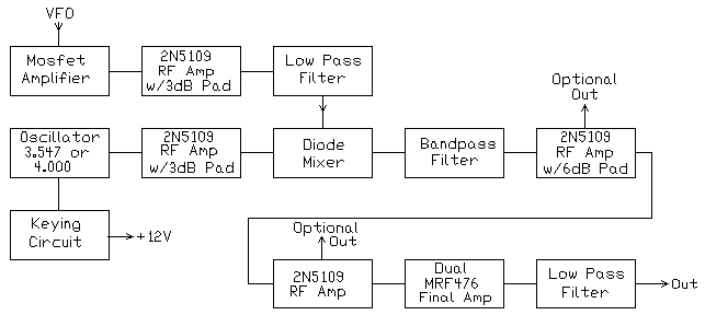


VFO Amplifiers/MixerThe mixer chosen was a commercial DBM, though a homebrew one would work just as well. The reason for this was the losses that occur when using a DBM. In this case the losses are a big advantage, because it blocks the backfeeding of the transmit signal back to the VFO in the receiver. The VFO is amplified/buffered by a MOSFET amplifier. This provides a high impedance connection to the VFO, leaving the drive level unaffected to the receiver mixer. Then a 2N5109 amplifier provides additional amplification and more importantly, proper matching to the diode mixer. A 3dB pad is used to ensure the proper matching, and with the low pass filter, also blocks the transmit signal from backfeeding into the VFO of the receiver. W6BKY has a receiver article at Hamradio-online that shows how to build this circuit on a universal printed circuit board. Check out http://www.hamradio-online.com//1999/jun/w6bky-16.html The low pass filter cleans up the signal to the mixer, providing a very nice picture on an oscilloscope for the mixer. This yields a very clean mixer output, helping to provide a very nice output signal. The combination mixer losses/low pass filter/3dB pad help keep the VXO RF from backfeeding to the receiver VFO. The VXO RF is not as strong as the output RF, but it needs to be kept isolated as well to prevent problems. Oscillator/Keying CircuitThe 12 Volts to the VXO is keyed, while all the amplifier circuits have power applied all the time. This limits the type of VXO circuit used, as several VXO circuits had a lot of chirp. The circuit in the VXO transmitter turned out to be the best one. Some of the component values used in the schematic are a little different, but the circuit is identical. The RF choke connected to the crystal is very important in setting the proper range of the crystal. Values between 47uH to 1uH should be handy to set the range desired for the crystal. The crystal pulls about 2-3 kHz, which is just acceptable for DX work, when they want you to transmit 3 kHz up from their transmit frequency. I've never worked a DX station that asked me to go down in frequency. This also allows a transmit incremental tuning function. An RIT could be included in the receiver VFO, and switched along with the keying circuit of the VXO. The keying circuit is the very common PNP transistor circuit seen in any Ham radio book or magazine. A 2N5109 amplifier is used with a 3dB pad to provide a good signal to the mixer and provide proper matching. The 3dB pad not only provides matching to the mixer, but also keeps the mixer products from causing problems in the VXO. In reality, there probably wouldn't be problems, but it is extra insurance. The VXO and 2N2222 amplifier circuit used in the original VXO transmitter could probably be used here with equal success. The output of the 2N2222 amplifier could tie directly into the diode mixer. Bandpass Filter and Final AmplifiersThe final amplifier is identical to the VXO transmitter. It was very easy to build "dead bug" style and worked very well. Two 2N5109 pre-amplifiers are used to get the maximum output from a MRF472 pair. The MRF472s are obsolete, but can be found in a lot of old CB transceivers and surplus outlets. Watch out when using the MRF476, as the pin connections are different from those shown in the pictures. The article in the 1988 ARRL Handbook (and others) also note the different connections for the MRF472 and the MRF476. The resistive Pi-Network pads are used to fine tune the output of the final amplifier pair. They also help kill any oscillations that may try to pop up and are a stabilizing factor in the final amplifier chain. Optional outputs are provided in my construction. That way it can be adapted to other QRP circuits or completed QRP transmitters. The MRF472s will drive 6146 amplifiers and old type Novice transmitters very well. In fact, in some cases the drive level from the MRF472s will have to reduced. If oscillations occur when driving tube type transmitters, just put a 50 ohm non-inductive resistor across the output of the MRF472/MRF476s. A good one is sold by BG Micro and can be found in their on-line catalog. Another more common option is to reduce the value of the grid resistor on the first amplifier tube until oscillation ceases, somewhere between 5K to 30K. |
|
|
|
|
Send E-Mail || Amateur Radio Receivers || CW Transmitter w/Superhet Receivers
