
|
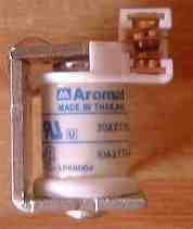
relays below all worked. The one of the left was too large for practical use, the main reason being its heavy weight. The one on the far right was the first one used with the stabilizer and was shipped in the first kits. Continued tests found another one that worked a lot better, but it is not pictured here. Next are a set of reed relays that did not work. They did move the frequency of the relay but not enough for effective stabilization. Some small relays did a good job. A couple I tested are shown. If you have a really good VFO that shows minimal drift, these relays can be effective stabilizers. A simple test setup consists of a couple of clip leads with alligator clips. A voltage variable power supply is used. Vary the voltage between 2 to 6 volts to get an indication of the range of the relay. Or check the resting voltage of the output of the stabilizer and vary the voltage two volts above and below that point. |

|
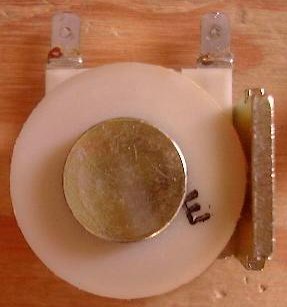
When the switching assembly is taken off, the relay should look like the stripped ones above. A metal rod should be in the middle of the coil, and a thick flange along one side. The magnetism that flows between the rod and the flange is utilized to control the frequency of the VFO. The relay on the left is larger than a T68-6, and pulls the VFO frequency 4 kHz with a 4 volt change (10 MHz). The relay supplied on the right was the first relay supplied with the kit. The third relay is about the size found in automobiles. If you want to experiment with different relays, check out Radio Shack and automobile parts stores. |
| Voerde | Dippoldiswalde | Witten | Jever | Steinbach-Hallenberg | Pocking | Propecia Erding | Propecia Müncheberg | Schrozberg |